First, the operation of CNC lathe
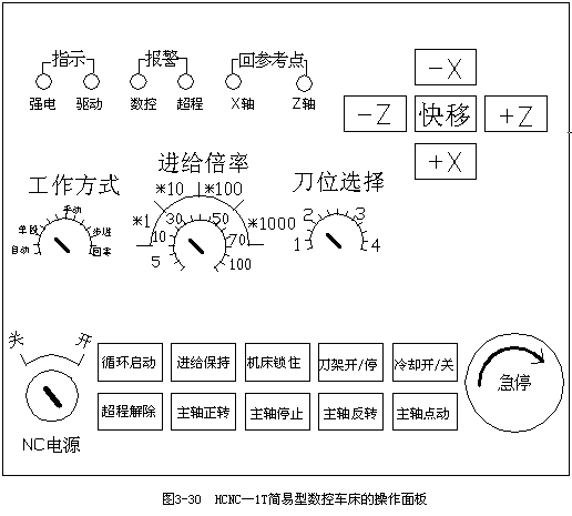
Although the functions of different CNC systems and CNC lathes are somewhat different, there are some changes in the operation panel of CNC lathes, but the basic functions and basic forms of the operation panels are similar. The following describes the operation panel of the HCNC-1T turning CNC system with the simple CNC lathe CJK6032, as shown in Figure 3-30. 
(1) After the power switch is closed, turn on the power switch on the operation panel with the key to turn on the CNC power. Also use the key to disconnect the CNC power.
(2) Emergency stop button During the operation of the machine tool, when an emergency situation occurs, press the emergency stop button, the servo feed and spindle operation will stop working immediately, and the CNC will enter the emergency stop state. When the emergency stop is to be released, it must be lifted in the direction of the arrow of the emergency stop button to release.
(3) Overtravel release button When an overtravel occurs on an axis, when exiting the overtravel condition, the overtravel release button must be pressed in the manual mode, and the coordinate direction direction button (+X, -X) is pressed at the same time. , +Z or -Z) reverse direction button to release the overtravel status.
(4) Working mode Select the band switch to select the working mode of the system through the working mode selection switch, including: automatic, single-segment, manual, stepping, zero return and other five working modes.
(5) Automatic mode When the working mode selection band switch is placed in this working mode, the machine tool control is automatically completed by the CNC, that is, it is automatically controlled by the NC program.
(6) Single-segment mode When the mode selection band switch is placed in the working mode, the program control will be carried out step by step, that is, after the machine is stopped for a period of time, press the cycle start button again to execute the next block, and after the execution is finished, Stop again. This method is generally used when debugging a program or trying to cut a workpiece.
(7) Manual/jog mode When the mode selection band switch is placed in this mode, press +X, -X, +Z or -Z, the machine will jog in the corresponding axial multiplication rate, release The button decelerates to a stop. When pressing +X, -X, +Z or -Z, press the quick-shift button at the same time, the jog speed is faster. This method is mainly performed when clamping, adjusting the workpiece, setting the tool parameters and other preparation work.
(8) Stepping mode When the mode switch is selected in the working mode, press +X, -X, +Z or -Z, and the machine will multiply the feedrate override in the corresponding axial direction by a multiple of the pulse equivalent. , release the button to stop. This method is mainly used when fine adjustment of the machine or precision setting.
(9) Zero return mode When the mode switch is selected in this mode, press +X, -X, +Z or -Z, and the machine will return to zero in the corresponding axis. Under normal circumstances, after the system is powered on or after exiting the CNC system, the machine axes must first be zeroed. During the zero return process, actions that move the axes (such as jog) are not allowed; all axes can be allowed. At the same time, the zero return operation is performed.
(10) Feedrate override In the automatic, jog and step mode, when the feedrate is too high, the feedrate override switch on the operation panel can be used to adjust the actual feedrate of the machine. This switch can provide 5%. , 10%, 30%, 50%, 70% and 100% six-tone revision ratio.
(11) Tool position selection After selecting the corresponding tool, press the “tool holder open/stop†button to manually transfer the tool selected by the user to the cutting position.
(12) Start of automatic start of cycle start.
(13) Feed keeps automatic operation paused. During the automatic operation mode, press the “Feed Hold†button, the machine motion axis decelerates to a stop, the execution of the program is suspended, and the tool and machine axis stop running. During the pause, the button indicator lights.
In the pause state, press the “Cycle Start†button again, the system will restart and continue to run from the paused position.
(14) Before the automatic operation starts, press the “machine lock†button, the recirculation starts, the coordinate position information changes, but the X-axis and Z-axis directions of the tool holder are not allowed to move (the tool holder can be indexed) . This function is used to verify the program.
(15) Coolant on/off Press this switch to turn on the coolant; when it is released, the coolant is off.
(16) Manual button for spindle forward/spindle stop/spindle reversal/spindle jog spindle rotation control. Spindle jog is generally used when the spindle speed is mechanically shifted after the gear is tested or the spindle is commissioned.
As for the specific operation of HCNC-1T turning CNC system with simple CNC lathe CJK6032, please refer to its instruction manual.
Second, CNC turning examples
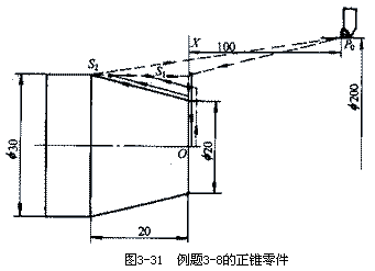
[Example 3-8] It is known that the blank is a bar of Φ30mm and the material is 45 steel. The CNC is turned into a positive cone as shown in Figure 3-31. 
The sequence of steps is as follows:
(1) Rough end face and outer conical face, leaving 1mm fine car balance.
(2) Finish the outer conical surface to size.
(3) According to the first car cone route, the final tool distance is S1=8mm and S2=16mm.
2. Selecting machine tools According to the requirements of the part drawings, the MJ-50 CNC horizontal lathe can be used. (2) Finish the outer conical surface to size.
(3) According to the first car cone route, the final tool distance is S1=8mm and S2=16mm.
3. Select the tool according to the processing requirements, select two tools, T01 is 90° rough turning tool, T02 is 90° precision turning tool. At the same time, the two knives are mounted on the automatic tool changer, and both are good knives, and their tool offset values ​​are input into the corresponding tool parameters.
4. Determining the amount of cutting The specific amount of cutting should be determined according to the performance of the machine, the relevant manual and the actual experience. The setting is divided into three passes. The first two backs are ap=2mm, and the last back is ap=1mm.
5. Determine the workpiece coordinate system to determine the intersection point of the right end of the workpiece at the intersection with the axis line O as the workpiece origin, and establish the X0Z workpiece coordinate system, as shown in Figure 3-31.
6. The program is programmed into a program list according to the instruction code and block format specified by the machine. The machining procedure of the workpiece is as follows:
NO1 G50 X200.0 Z100.0; Set the workpiece coordinate system
N02 M03 S800 T0101; Take the No. 1 90° partial knife and prepare the roughing
N03 G00 X32.0 Z0; Quick approach to workpiece
N04 G01 X0 F0.3; rough end face
N05 Z2.0; axial retraction
N06 G00 X26.0; Radial quick retraction to the first rough pass
N07 G01 Z0 F0.4; take the knife to the first rough car cone
N08 X30.0 Z-8.0; First rough car cone S1
N09 G00 Z0; The first rough car forward cone S1 quickly returned
N10 G01 X22.0 F0.4; take the knife to the second rough car cone
N11 G01 X30.0 Z-16.0; Second rough car cone S2
N12 G00 X200 Z100.0 T0100; After the second rough car cone S2, quickly return to the tool change point
N13 T0202; Take the No. 2 90° partial knife to prepare the finishing car
N14 G00 X30 Z0; Quickly move to (X30, Z0)
N15 G01 X20.0 F0.4; Finishing end of the car to the right taper of the part
N16 X30.0 Z-20.0; Finishing cone to part size
N17 G00 X200.0 Z100.0 T0200 M05; Quick retraction to the starting point
N18 M02; End of program
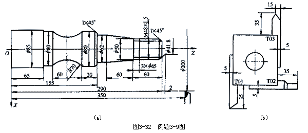
[Example 3-9] The parts shown in Figure 3-32(a) are finished on the CK7815 CNC lathe. The Φ85mm outer cylindrical surface in the figure is not machined. Try to compile its finishing program. N02 M03 S800 T0101; Take the No. 1 90° partial knife and prepare the roughing
N03 G00 X32.0 Z0; Quick approach to workpiece
N04 G01 X0 F0.3; rough end face
N05 Z2.0; axial retraction
N06 G00 X26.0; Radial quick retraction to the first rough pass
N07 G01 Z0 F0.4; take the knife to the first rough car cone
N08 X30.0 Z-8.0; First rough car cone S1
N09 G00 Z0; The first rough car forward cone S1 quickly returned
N10 G01 X22.0 F0.4; take the knife to the second rough car cone
N11 G01 X30.0 Z-16.0; Second rough car cone S2
N12 G00 X200 Z100.0 T0100; After the second rough car cone S2, quickly return to the tool change point
N13 T0202; Take the No. 2 90° partial knife to prepare the finishing car
N14 G00 X30 Z0; Quickly move to (X30, Z0)
N15 G01 X20.0 F0.4; Finishing end of the car to the right taper of the part
N16 X30.0 Z-20.0; Finishing cone to part size
N17 G00 X200.0 Z100.0 T0200 M05; Quick retraction to the starting point
N18 M02; End of program

(1) First cut the outer contour surface from right to left. The route is: chamfer → actual outer circle of cutting thread → cutting taper part → turning Φ62mm outer circle → chamfering → turning Φ80mm outer circle → cutting arc part → car Φ80mm Outer circle.
(2) Cut a groove of 3 mm × Φ 45 mm.
(3) The thread of the car M48×1.5.
2. Select the tool and draw the tool layout. Three tools are required according to the machining requirements. The tool layout is shown in Figure 3-32(b). T01 cutter outer circle, T02 knife slot, T03 cutter thread. For the tool setting, use the T-knife as the reference tool to measure the deviation of the other two tools with respect to the reference tool, and input their tool offset values ​​into the tool-biasing unit of the corresponding tool. (2) Cut a groove of 3 mm × Φ 45 mm.
(3) The thread of the car M48×1.5.
In order to avoid collision between the tool and the machine tool, workpiece and fixture during tool change, the tool change point should be selected correctly. In this example, the tool change point is selected as A (X200, Z350) point.
3. Select the cutting amount and the cutting amount is shown in Table 3-4.
Table 3-4 Turning amount used in Example 3-9
Cutting surface | Cutting amount | |
Spindle speed S/r.min-1 | Feed rate f/mm.r-1 | |
Outside the car | 630 | 0.15 |
Grooving | 315 | 0.16 |
Thread | 200 | 1.50 |
NO1 G50 X200.0 Z350.0; Set the workpiece coordinate system
N02 M03 S630 T0101 M08; The spindle is rotating forward, the speed is 630r/min, the No. 1 knife is selected, and the cutting fluid is opened.
N03 G00 X41.8 Z292.0; Fast forward to (X41.8 Z292) point
N04 G01 X47.8 Z289.0 F0.15; chamfering, feed rate is 0.15mm/r
N05 U0 W-59.0; car Φ47.8mm thread diameter
N06 X50.0 W0; radial retraction
N07 X62.0 W-60.0; car 60mm long cone
N08 U0 Z155.0; outer circle of car Φ62mm
N09 X78.0 W0; radial retraction
N10 X80.0 W-1.0; chamfer
N11 U0 W-19.0; outer circle of car Φ80mm
N12 G02 U0 W-60.0 I63.25 K-30.0; car Shun arc R70 (center of the circle relative to the starting point, I, K parameter values ​​can also be used R70 generation)
N13 G01 U0 Z65.0; outer circle of car Φ80mm
N14 X90.0 W0; radial retraction
N15 G00 X200.0 Z350.0 M05 T0100 M09; Rewind to the tool change point, the spindle stops, cancels its tool compensation, cutting fluid off
N16 M06 T0202; Change the No. 2 knife and perform its tool compensation
N17 G00 X51.0 Z230.0 M03 S315 M08; fast forward, spindle forward rotation, speed 315r/min, cutting fluid on
N18 G01 X45.0 W0 F0.16; Grooving, feed rate is 0.16mm/r
N19 G04 X5.0; delay 5s
N20 G00 X51.0; radial quick retraction
N21 X200.0 Z350.0 M05 T0200 M09; Rewind to the tool change point, the spindle stops, cancels the tool compensation, cutting fluid off
N22 M06 T0303; Change the No. 3 knife and perform its tool compensation
N23 G00 X52.0 Z296.0 M03 S200 M08; fast forward, spindle forward rotation, speed is 200r/min, cutting fluid is on
N24 G92 X47.2 Z231.5 F1.5; Thread cutting cycle, feed rate 1.5mm/r
N25 X46.6;
N26 X46.2;
N27 X45.8;
N28 G00 X200.0 Z350.0 T0300 M09; Quick return to the starting point, cancel the tool compensation, cutting fluid off
N29 M05; spindle stop
N30 M02; End of program
We are professional customized metal fashionable small cosmetic mirror,pocket mirror, Compact Mirror, tin pocket mirror, makeup mirror. Usually it is use for promotional gift and advertising gift. It is to carry conveniently for people. Usually we make it by zinc alloy material, in order to make is beautiful, we can plating color on the surface, such as gold, silver, nickel, antique silver, copper, brass and so on.
Compact Mirror
Compact Mirror,Silver Compact Mirror,Compact Makeup Mirror,Small Compact Mirror
Shenzhen MingFengXing Art & Craft Products CO., LTD. , https://www.mf-gift.com